
SDR CTF: Commercial FM with GNU Radio
If you felt a little let down by the simple act of using a GUI like SDRSharp or GQRX to listen to commercial FM and wanted a little more challenge, then give GNU Radio a try. You will learn a lot about Digital Signal Processing and Software Defined Radio in the process. Things are going to get a little theoretical at first.
I/Q Signals
The magic to the RTL SDR (and other SDR platforms) is that it basically streams out I/Q data that can be processed by your CPU and converted into pretty waveform graphs, and waterfalls, and audio signals. I/Q, also In-phase/Quadrature is an complex number that describes the signal in phase and amplitude format. It contains more information than a simple series of floating-point numbers, at the cost of needing a bit more storage and sometimes harder for you to visualize. There are some nicer pictures and explanations of I/Q here at http://witeboard.ping.se/SDR/IQ.
A Bit About GNU Radio
GNU Radio is a Digital Signal Processing framework for python. With it, you can write python programs that interact with radio devices like the RTL SDR and other SDR platforms, or it can simply process data collected from other sources. It doesn't have to be RF, despite having "Radio" in its name.
We'll be using GNU Radio Companion to interact with GNU Radio. This is a GUI tool that allows you to create visual signal flow diagrams. It will then render these diagrams into python code that performs the analysis that you've drawn out on the screen.
Receiving Commercial FM is the "Hello World" of GNU Radio, let's get started. First, you'll need GNU Radio and GNU Radio Companion installed on your system of choice. You can use a bootable linux like Pentoo that already has these tools installed if you'd like.
Start GNU Radio Companion with: gnuradio-companion
You should start up with something like this:
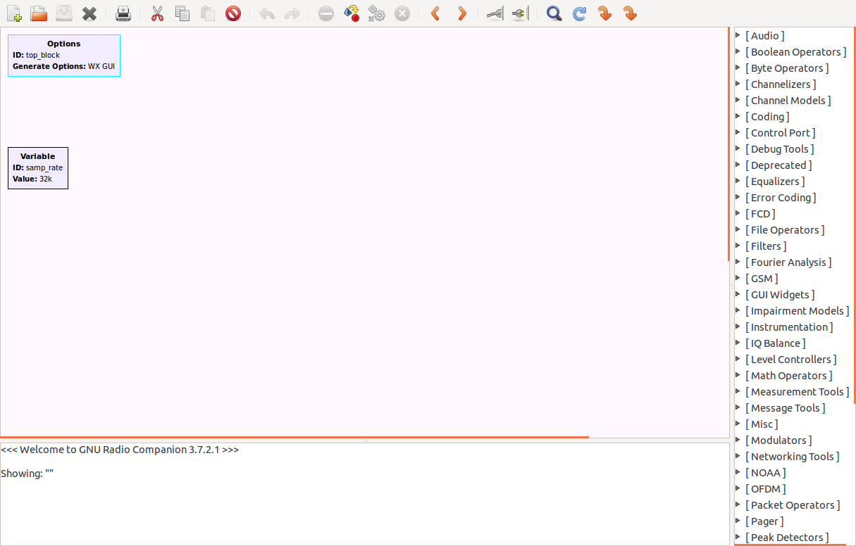
The very basics: double-click on a box/module to edit its parameters, use the menu on the right to find modules and drag them out onto the flow diagram, and click on two modules that you want to connect. We'll start with a source. Open up the "Sources" menu and drag out the RTL-SDR source. Note that the title font is red, indicating that it's pre-requisites are not met; it will turn black when it is happy. Observe the blue "out" tab. To make flows work, you need to hook the "out"s to "in"s. The blue color tells you that the module outputs a complex I/Q steam, and it will only connect to blue "in" tabs.
Next, take a look at the box labelled "Variable." Double click to edit it's parameters. We'll set the sample_rate to 2M by entering 2e6 into the Value field.
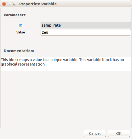
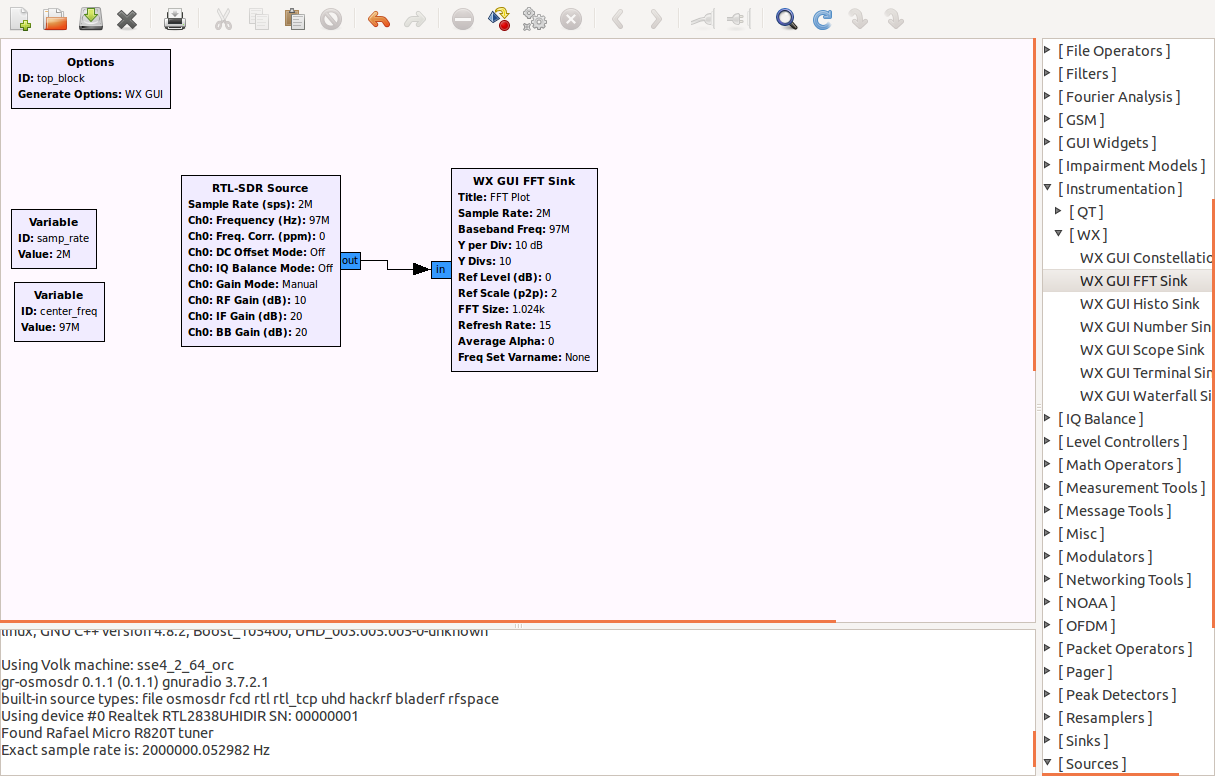
Next create a new variable by copy/pasting samp_rate. We are going to call this one center_freq and set the value to be 97e6. We will reference this variable in the RTL-SDR source. Double-click on the module to open up it's parameters and set the CH0 frequency to center_freq.

We'll create a valid flow diagram by providing somewhere to send the stream. In this case we'll add some visualization. Look in the menu on the right under Instrumentation, then WX, then drag out "WX GUI FFT Sink" onto the flow diagram. Click on the "RTL-SDR Source", and then click on "WX GUI FFT Sink" and you will connect the two modules, and they should turn from red to black.
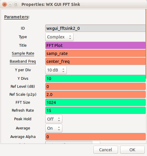
Double-click on the FFT Sink and set the following parameters:
Now your flow diagram should look something like this:
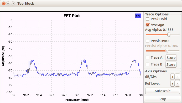
Now we have something that will run. Click on the "execute" button or hit F6. This will ask you to save a .grc file. This is just the flow-diagram. It will also build a python program and execute it. You should see an FFT plot appear similar to:
Shifting Frequency via Multiplication
We've seen how the DC Bias introduces an artificial peak at our center tuned frequency. We often use offset tuning to avoid this in other software, and we're going to do the same thing here. Create a new variable, call it "channel_freq" and set it to the frequency of a known local station.
Imagine the stream of values coming in through the stream. If you multiply each value by a constant, you will effectively amplify the signal. If instead of a constant, you multiply by an appropriate sine wave you instead shift the frequency of the signal (like in a Heterodyne receiver.) We're going to create a signal by opening up the "Waveform Generators" menu on the right and dragging out a "Signal Source" into the flow diagram.
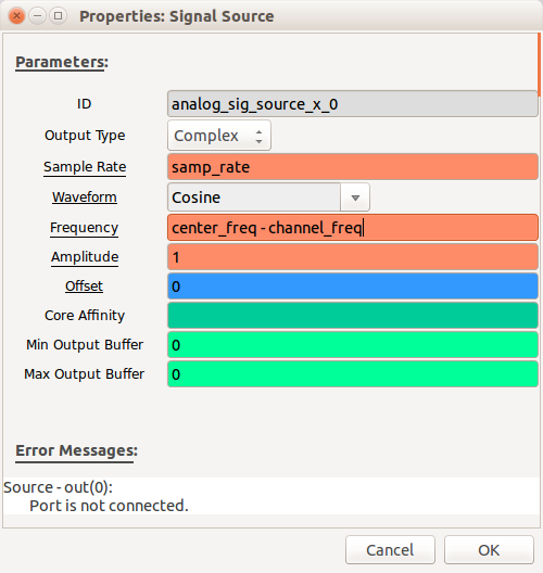
First, notice how it pre-populates samp_rate for the sample rate. Set the Frequency to be: center_freq - channel_freq
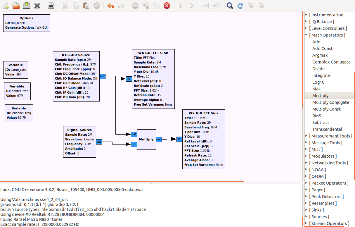
Next, open up the "Math Operators" menu and drag a "Multiply" module out into the flow. Copy/Paste another FFT sink and connect the modules like this:
Pretty pictures are nice and all, but we want to listen to the radio. Right now we've got a stream of I/Q values arriving at 2 million samples per second. Somehow we still need to demodulate wideband FM in a stream of floating numbers arriving at 48 thousand samples per second, which most sound cards should support.
The Basic Digital Signal Processing System
Typical generic signal processing systems consist of:
- low-pass anti-aliasing pre-filter
- sampler operating above the nyquist frequency
- quantizer - converts sampled signal to a finite level (e.g. 16-bit levels)
- encoder - converts quantized values to bit
- things that process the stream
- decoder - converts processed bit-stream to discrete quantized values
- reconstruction filter - builds a staircase approximation of the resulting signal
The low-pass filter is used for anti-imaging and removes replicas. In our process so far, we're in the "things that process the stream" section, but require a bit of pre-filtering before we feed the signal to the FM demodulator. We'll use a 75kHz low-pass filter with a transfer width of 25kHz. From the "Filters" menu, drag a "Low Pass Filter" out into the flow diagram. Set the Cutoff frequency to 75e3 and the transition width to 25e3. But we need to take a little break and look at a bit more theory...
Decimation and Interpolation
Decimation is the reduction of signal length by discarding samples. Imagine the signal has values: 0, 1, 2, 3, 4, 5, 6, 7, 8, 9, 10. If you decimate by 2 (basically cut it in half) the signal would become 0, 2, 4, 6, 8 ,10. If you decimate the original instead by 3 you have 0, 3, 6, 9
Interpolation increases the length of the signal by inserting samples. These inserted samples could be zeroes, replication of the current value, or an average of the samples.
One would decimate and interpolate a signal to convert its sample rate. You can only decimate and interpolate an integer number of times. So if you need to alter a sample rate by a rational value, you mix decimation and interpolation to get close to the value that you need.
While you have the parameters for the low-pass filter open, note the colors of the fields. They match the color-coding of the inputs and outputs of the module. While the frequency and transition width are orange and will accept a floating value, the decimation field is green, and will only accept an integer.
So?
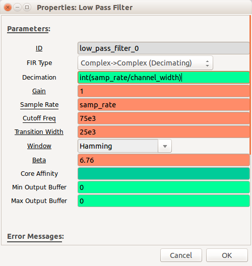
We will be feeding the output of this filter into a Wide FM demodulator so we need to reduce the bandwidth/sample-rate of the signal down from 2 MHz down to 200kHz. Create a new variable, call it channel_width and set it's value to 200e3. So in the Decimation field we'll use a formula to calculate this rate for us: int(samp_rate/channel_width)
Now we have a signal at 200kHz, the filtered bandwidth of Wideband FM. It expects a 480kHz which we'll decimate by 10 down to the 48kHz that we can feed into the sound card. So we need to run this 200kHz signal through a 12/5 decimation/interpolation process. We'll accomplish this using a resampler. From the "Resampler" menu on the right, drag a "Rational Resampler" out into the flow, setting the Interpolation to 12 and Decimation to 5.
Finally Demodulation
Now we've got a 480kHz I/Q signal that's been filtered to include just the FM signal that we're after. Under "Modulators" drag a "WBFM Receive" module out into the flow. Note the blue input and orange output. Set the Quadrature rate to 480e3 and the decimation rate to 10.
Finally, open up open up the "Audio" menu and drag out an "Audio Sink" into the flow. Note how it has the sample rate set to "samp_rate." This is 2 million samples per second which is no good for audio. Pull down and select 48kHz.
Connect up the flow to look something like this:
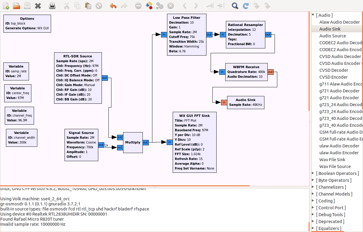
Now when you execute, you should be hearing the station that you have identified in channel_freq, as long as it's within 2MHz of the center_freq.
- Log in to post comments